
Koji MATSUMOTO
Tokyo Institute of Technology

Moe YONEHANA
Kajima Corporation

Junichiro NIWA
Tokyo Institute of Technology
| Yoshida Award for thesis 2013 | ||
| SHEAR BEHAVIOR OF RC DEEP BEAMS WITH SOLID CIRCULAR CROSS SECTION UNDER SIMPLY SUPPORTED CONDITION AND ANTI-SYMMETRIC MOMENT | ||
| PDF Version | ||
Koji MATSUMOTO Tokyo Institute of Technology |
Moe YONEHANA Kajima Corporation |
Junichiro NIWA Tokyo Institute of Technology |
| Linear reinforced concrete (RC) members such as piers and piles are often designed with a circular cross section. The shear span to effective depth ratio (a/d) of such members is sometimes less than 2.0 (short beams) or 1.0 (deep beams). Although the shear resistance mechanism of RC deep beams is different from that of slender beams, the applicability of existing design methods to RC deep beams with circular cross section has not been discussed. Besides, when pile members are subjected to seismic loads, an anti-symmetric moment develops in the range of a/d<2.0 as a result of dynamic earth pressure. However, there have been almost no studies on the shear behavior of RC deep beams with circular cross section subjected to an anti-symmetric moment.
In this study, loading tests were carried out on RC deep beams with circular cross section. The experimental parameters were the support arrangement, number of longitudinal reinforcement bars and stirrup ratio. Table 1 lists the experimental cases and Fig. 1 outlines the specimens, respectively. |
||
Table 1: Experimental cases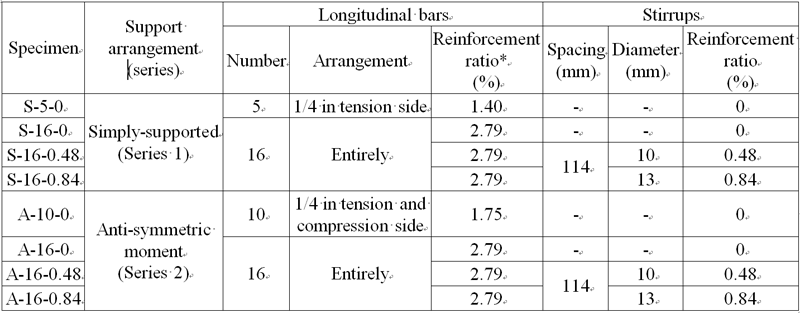 |
||
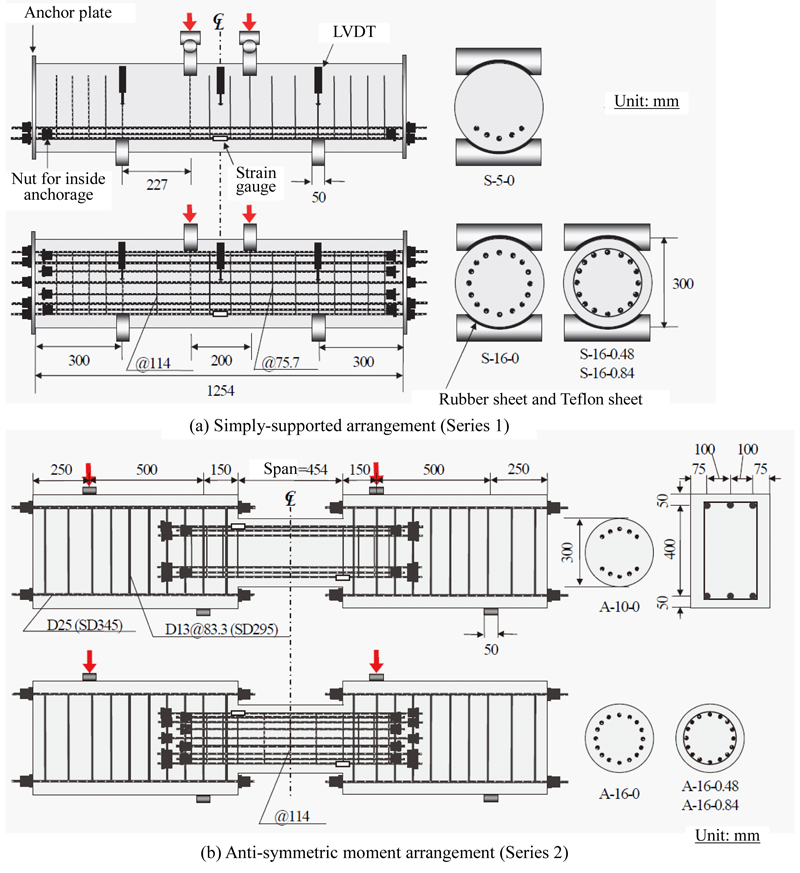 Fig. 1: Outline of specimens |
||
| Experimental values of applied shear force obtained in the tests are corrected by excluding the effect of concrete strength. Figure 2 shows the corrected shear force-mid span deflection relationships (Series 1) and corrected shear force-relative displacement relationships (Series 2) obtained in the experiment. With an increasing number of longitudinal bars and increasing stirrup ratio, the shear capacity increases in both the simply-supported condition and the anti-symmetric moment condition. The shear capacity of a specimen subjected to the anti-symmetric moment is much smaller than that of a simply-supported specimen with the same a/d. |
||
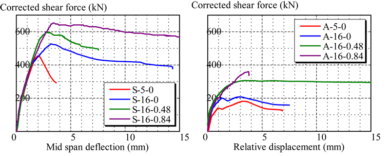 Fig. 2: Corrected shear force-mid span deflection and relative displacement relationships |
||
| Strain distributions in the region where the compression strut formed were measured using acrylic bars embedded in the specimens, as shown in Fig. 3. Figure 4 shows the stress distributions in the struts as converted from the strain distributions using existing stress-strain models of concrete. In specimens S-16-0.48 and S-16-0.84, which had stirrups, no concave shape is observed as is shown near the loading point in specimens S-5-0 and S-16-0 because the ultimate strain of the concrete is enhanced by the confinement effect of the stirrups. The stress distributions when subjected to an anti-symmetric moment are relatively small compared to the cases under simply-supported condition, indicating that contribution of the compression strut to shear resistance is reduced.
|
||
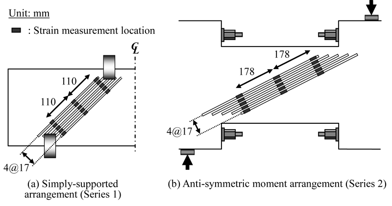 Fig. 3: Locations of acrylic bars and strain measurement |
||
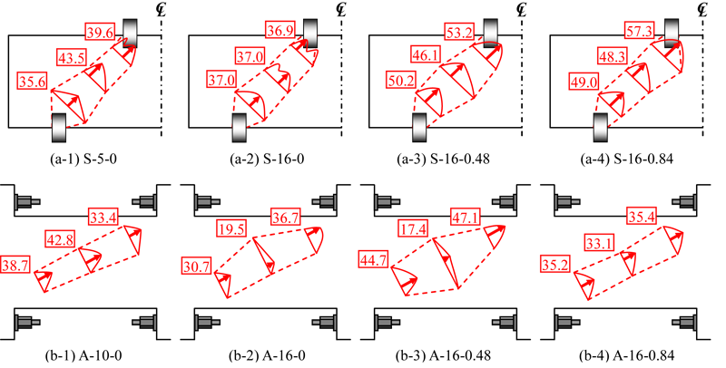 Fig. 4: Stress distribution in compression struts at 95% of the maximum load (unit: N/mm2) |
||
|
The authors propose the mechanical model shown in Fig. 5 to explain the shear resistance mechanism of RC deep beams when subjected to an anti-symmetric moment. The state of forces is symmetrical with respect to point O and the flow of compression force due to the strut forms such that it encloses the diagonal crack. Since the bending moment is reversed at mid span, a section of concrete in compression forms at either end of the diagonal crack. From the force and moment equilibrium, the following equations can be obtained:
|
||
 |
||
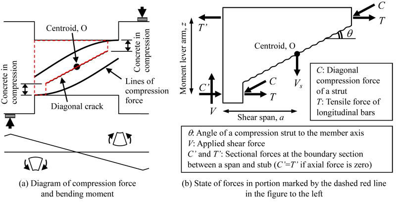 Fig. 5: Shear resistance model of RC deep beams subjected to anti-symmetric moment |
||
|
By solving Eq. (2) for V, Eq. (2) becomes
|
||
 |
||
|
The first and second terms on the right side of Eq. (4) represent the shear resistance contributed by the compression strut and stirrups, respectively. That is, the mechanical model shown in Fig. 5 indicates that the total shear resistance is a summation of the resistance contributed by the compression strut and the stirrups.
|
||
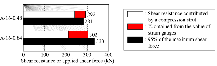 Fig. 6: Comparison of experimental values with summation of shear resistance force by compression strut and stirrups |
||
| In Fig. 6, the summed shear resistance contributed by the compression strut and the tensile resistance of the stirrups, Vs, are compared with the shear force applied in the experiment. The shear force borne by the compression strut is the vertical component of the force calculated by integrating the stress distributions shown in Fig. 4. As mentioned before, in the case of RC deep beams subjected to an anti-symmetric moment, the contribution of the compression strut to shear resistance is rather small compared to the total shear force. However, when summed with the tensile resistance of the stirrups, it approximates the experimental values. Consequently, in specimens A-16-0.48 and A-16-0.84, it is supposed that the stirrups contribute a significant shear strengthening effect because of the effect of the shear resistance mechanism illustrated in Fig. 5. | ||