


Keiichi AOKI (Central Nippon Expressway Co., Ltd.), Shinya WATANABE (Japan Construction Method and Machinery Research Institute), Takashi SANGA (Sumitomo Mitsui Construction Co., Ltd.), Kenichi MIYANAGA (West Nippon Expressway Co., Ltd.) and Hiroshi MUTSUYOSHI (Saitama University)
Abstract
There have been reports around the world of tensioning cable failure in post-tensioned prestressed concrete (hereinafter, PC) bridges as a result of incomplete packing of the cable sheath with grout. In this study, we investigate the condition of concrete, rebars, PC cables, and PC grout, as well as the packing of the sheath with grout, in a bridge girder fabricated more than 40 years ago. Further, we carry out loading tests on the beam and nonlinear analysis of the PC bridge girder. According to the experimental results, there is no material deterioration and the ultimate load exceeds the design ultimate load by approximately 20 percent.
1. Specifications of tested PC girder
1.1 PC girder summary
The PC girder tested in this investigation is a post-tensioned PC T-girder completed in 1971. It originally formed part of a bridge along the Hokuriku expressway located within 100 m of the Japan Sea shoreline. The girder was removed from the bridge in 1997 when the design live load was upgrade to the B specification from TL-20. Thereafter, the girder was transferred to Fuji City, Shizuoka Prefecture. Accordingly, 41 years have now passed since its fabrication. Photo 1 shows the girder being removed, while Photo 2 illustrates how it has been stored. Figure 1 is a structural drawing of the girder.
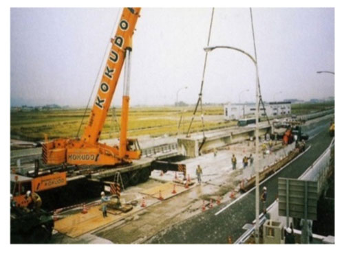
Photo 1 Removal of beam
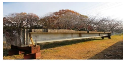
Photo 2 Post-removal aging
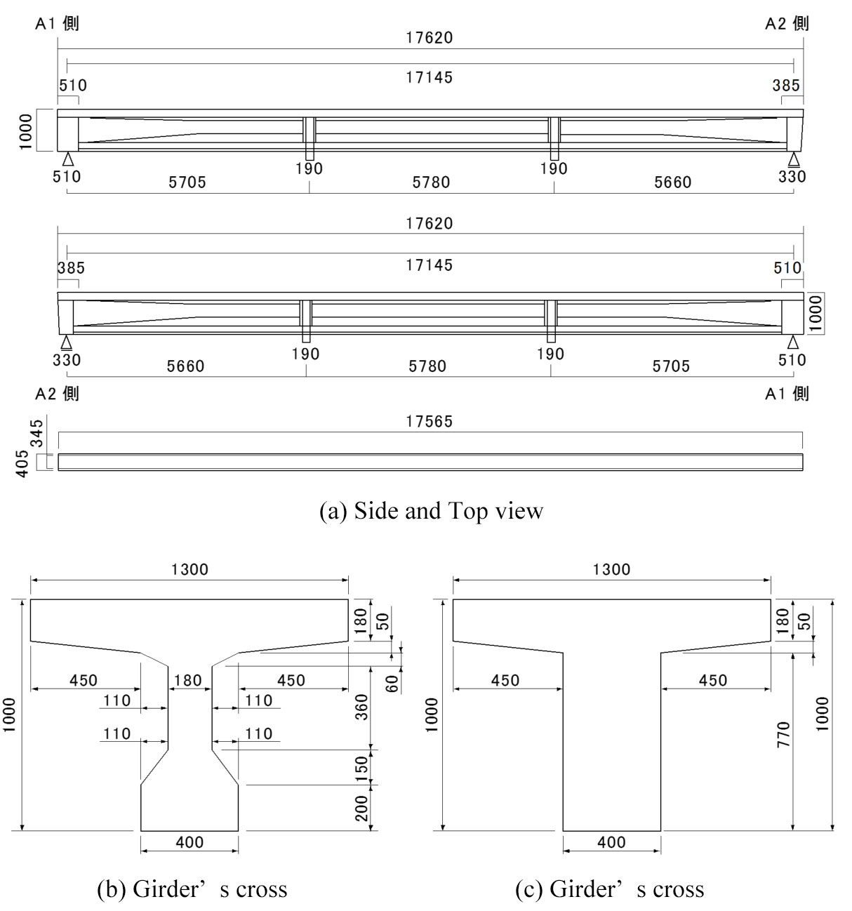
Fig. 1 Structural drawing
2. Material properties of 40-year-old PC girder
2.1 Physical properties of concrete
Cores were removed from the girder and tested for compressive strength and static modulus of elasticity. The average compressive strength of the core concrete was 48.7 N/mm2, exceeding the design strength of 40 N/mm2 by more than 22%. This result shows that concrete aging is not exhibited in its compressive strength and static modulus of elasticity.
2.2 Mechanical properties of rebars
The cover concrete was chipped away to remove sections of main rebar from under the flange at the span center. Tensile tests were carried out on the removed rebars (D13). All test pieces met the Japan Industrial Standard (JIS). Furthermore, no corrosion or pitting caused by aging were noted.
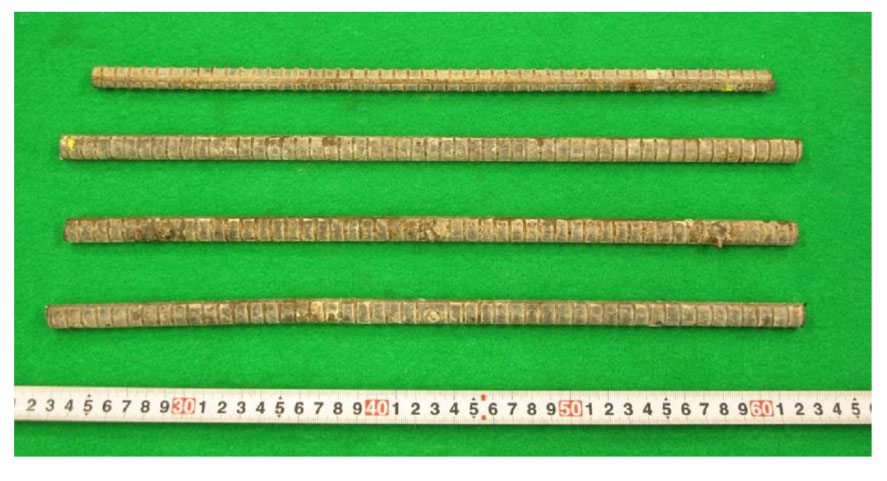
Photo 3 Rebar test pieces
2.3 Mechanical properties of tensioning wires
Cover concrete, steel sheath, and PC grout were removed from the span center and the tensioning wires extracted. Photo 4 shows the removed wires. Red rust, but no pitting corrosion, was identified on the wires.
Tensile tests were carried out on four of the wires. The Specifications for PC Highway Bridges set the allowable elongation at over 5%, but the three of the tested wires exhibited elongation of no more than 5%. Therefore, we also figured elongation inferior 0.5% by aging.
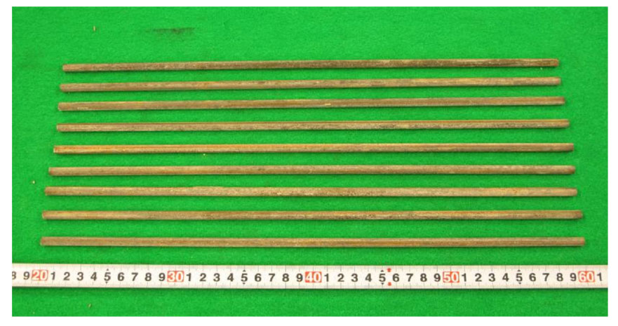
Photo 4 Post-tensioning wires (C2 wires)
3. Bending test of PC girder
3.1 Experimental outline
The intention of this test was to confirm the flexural capacity of the PC girder. Prior to testing, five PC wires (φ7 mm Å~ 12 mm) were individually cut with the goal of simulating corrosion or failure of the wires resulting from lack of grout. Figure 2 shows the experimental procedure. Photo 5 illustrates the test arrangement and Fig. 2 outlines the test procedure used.
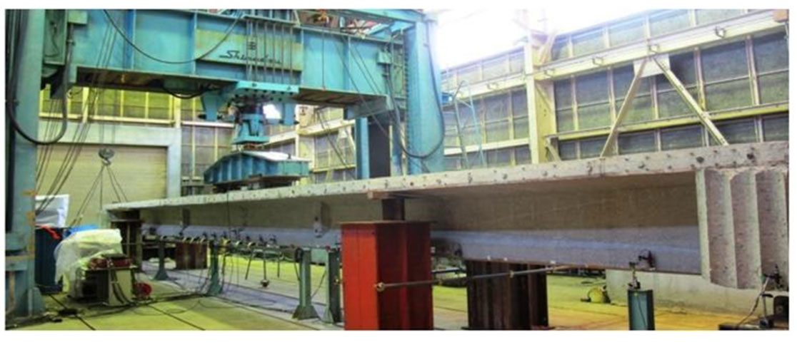
Photo 5 Load test arrangement
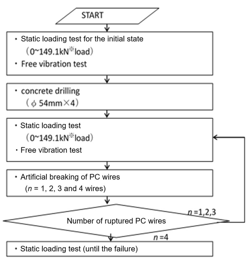
Fig. 2 Load test procedure
3.2 Test results
3.2.1 Impact of cutting post-tensioning wires
Figure 3 shows how the strain on the concrete surface under the PC girder increased as the first to fourth wires were cut.
The area influenced by cutting the first and second wires were from ±300 mm to ±1200 mm, as indicated by the increasing strain level. This area of influence became ±1500 mm upon cutting the third and fourth cables. The previous report on cutting PC wires stated that the influenced region is almost the same as the effective bond length of the PC wires (in this study, 65φ). The influence of cutting the wires in this test was confirmed to extend over this length, which might have been caused by the packing condition of the grout. That is, one of the causes of the widespread influence may be lack of grout packing.
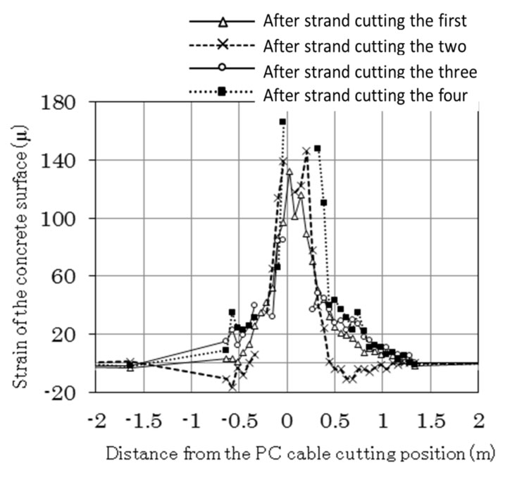
Fig. 3 Influence of cutting tensioning wires
3.2.2 Failure properties
The beam was tested to failure after the fourth wire was cut. The crack width in the center quickly increased. The girder then broke apart, accompanied by the sound of parting wires and rebars, when the load was about 168 kN and the deflection was 199.48 mm. Photo 6 shows the situation after failure.
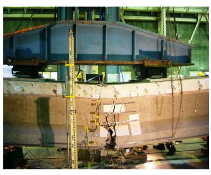
Photo 6 Situation at failure
4. Influence of failed post-tensioning wires in real bridges
In the experiment, some rebars had been cut as a result of drilling cores to cut the post-tensioning PC wires. In a real structure, the PC wires would part, in some cases, after corrosion caused by lack of grout packing. To investigate the real case, the case of breaking only the post-tensioning PC wires was simulated. We also analytically considered the influence of bending proof stress with no drilled cores and sectional breaking area.
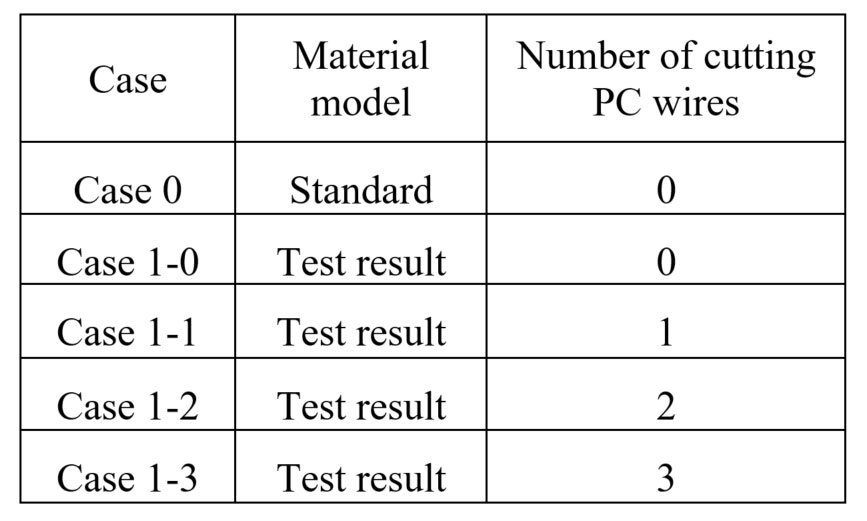
The material models used in this analysis were based on experimental values and standard value models (Table 1). In the analysis, a model which represents the influence of rupture of PC wires was used. That is, PC wires within 1.5 times of the effective bond length from the rupturing location was not considered. The rupturing location of PC wires in the analysis was the same as that in the experiment.
The result of analysis indicates that, in the cases 0 and 1-0, crushing of concrete causes the rupturing of PC wires in the girder. In the cases 1-2 and 1-3, two PC wires in the girder were ruptured due to the crushing of concrete.
Figure 4 shows the relationships between load and displacement at the girder center.
The design live load at the time of construction (TL-20) was 149.1 kN. The current value of design live load (the B-live load) is 166.0 kN. The case with the experimental material model in which three post-tensioning wires were cut (Case 1-3) indicates that the ultimate load remains higher than the design load.
Consequently, the flexural failure load of the case in which three PC wires are ruptured is still higher than the ultimate design load specified in the Specifications for Highway Bridges, Japan Road Association. Safety against failure is therefore satisfied when the actual experimental values are selected for the material model.
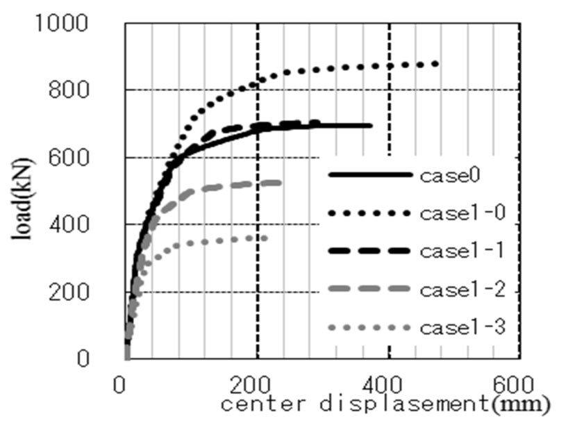
Fig. 4 Load-displacement relationship
Table 1 Analysis cases