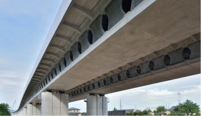
Figure 1 Completion View (General Section)
Client: East Nippon Expressway Company Limited
1. Overview
The Okegawa Viaduct is located between the Okegawa Kano and Shiraoka Shobu interchanges of the Metropolitan Inter-City Expressway in Saitama Prefecture, Japan. It is a multi-span continuous PC Box girder bridge comprising of eight spans and has a total length of 3089m. The precast segments, each consisting of a U-shaped core with two butterfly web panels and a horizontal rib, were erected span-by-span for the first time in the world. This work method achieved a reduction in the total number of segments to be produced/transported/erected and a shortened work process.

Figure 1 Completion View (General Section)
|
Type: 5-13 span continuous butterfly
web PC box girder bridge Length: 3,089m (Inbound: 1530m, Outbound:1559m) Standard Span Length: 45.0m (Maximum:53.0m) Client: East Nippon Expressway Company Limited |
Design Superstructure: Sumitomo Mitsui Construction Co., Ltd. & P. S. Mitsubishi Construction Co., Ltd. JV Substructure: Doyu Daichi Co., Ltd. Construction Superstructure: Sumitomo Mitsui Construction Co., Ltd. & P. S. Mitsubishi Construction Co., Ltd. JV Substructure: Nishimatsu Construction Co., Ltd. & Obayashi Corporation |

Figure 2 General viewl
3. Features of the Bridge
(1) Segment Division and Butterfly Web1)
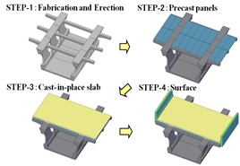
The segments were produced at an offsite plant to ensure quality control, so they needed to be limited in weight to allow transportation on public roads. As a measure to reduce the total number of segments, a U-shaped core segment was designed with ribs to enable post-erection laying of the upper slab. This design made it possible to reduce the number of segments to approximately two-thirds in comparison with conventional full cross section segments, and also to shorten the process of production, transportation, and site erection (Figure 3).
The adoption of butterfly-shaped web panels reduced the weight of the superstructure by 3%. This also reduced the erection weight of each span. Further, the speed of segment jointing work was improved dramatically because of the reduced area of adhesive coating on each segment due to the discontinuity of the web (Figure 4).
 |
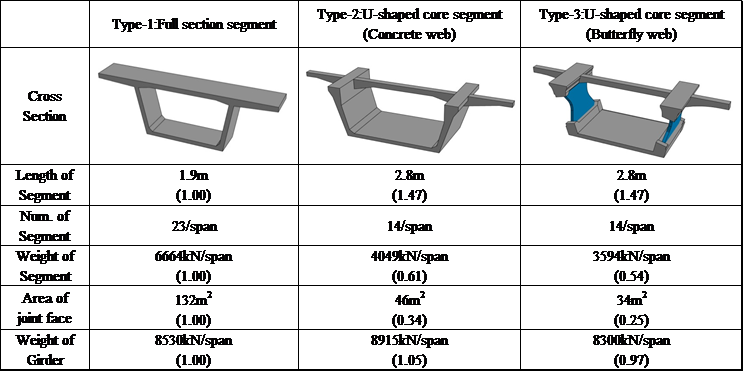 |
| Figure 3 Main Girder Construction Procedure | Figure 4 Comparison of Segment Designs |
(2) Interlocking Pier Reinforcement Arrangement
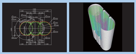
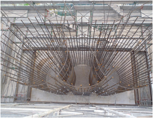
The seismic resistance of the RC bridge piers was improved by adopting an interlocking reinforcement arrangement structure with round lateral ties to obtain a concrete constraining effect. By partially overlapping the round lateral ties, thereby rationalizing the reinforcement arrangement with the elimination of intermediate lateral ties, workability was improved and the construction period reduced (Figure 5 and Figure 6).
 |
 |
| Figure 5 Interlocking Pier | Figure 6 Reinforcement Arrangement of Pier |
(3) Measures for Mass Concrete of Pier
Various measures for handling the mass concrete of the piers were carried out: utilization of low heat generation, low shrinkage Portland blast-furnace cement (which restrains the temperature rise by 10% compared to the time of a standard concrete use) and installation of polyethylene foam insulation around the formwork (to restrict the temperature differential to less than 8°C), etc. With careful construction work, particularly with regard to curing method, etc., the RC piers were completed to a high standard of quality, with cracking suppressed and an attractive finish.
(4) Aesthetic Considerations
The aesthetics of the viaduct design were considered as follows.
- The surface of the web and the pier edge were matched (without girder overhang) to maintain a continuity of line in this low-height continuous bridge (pier height = 10m).
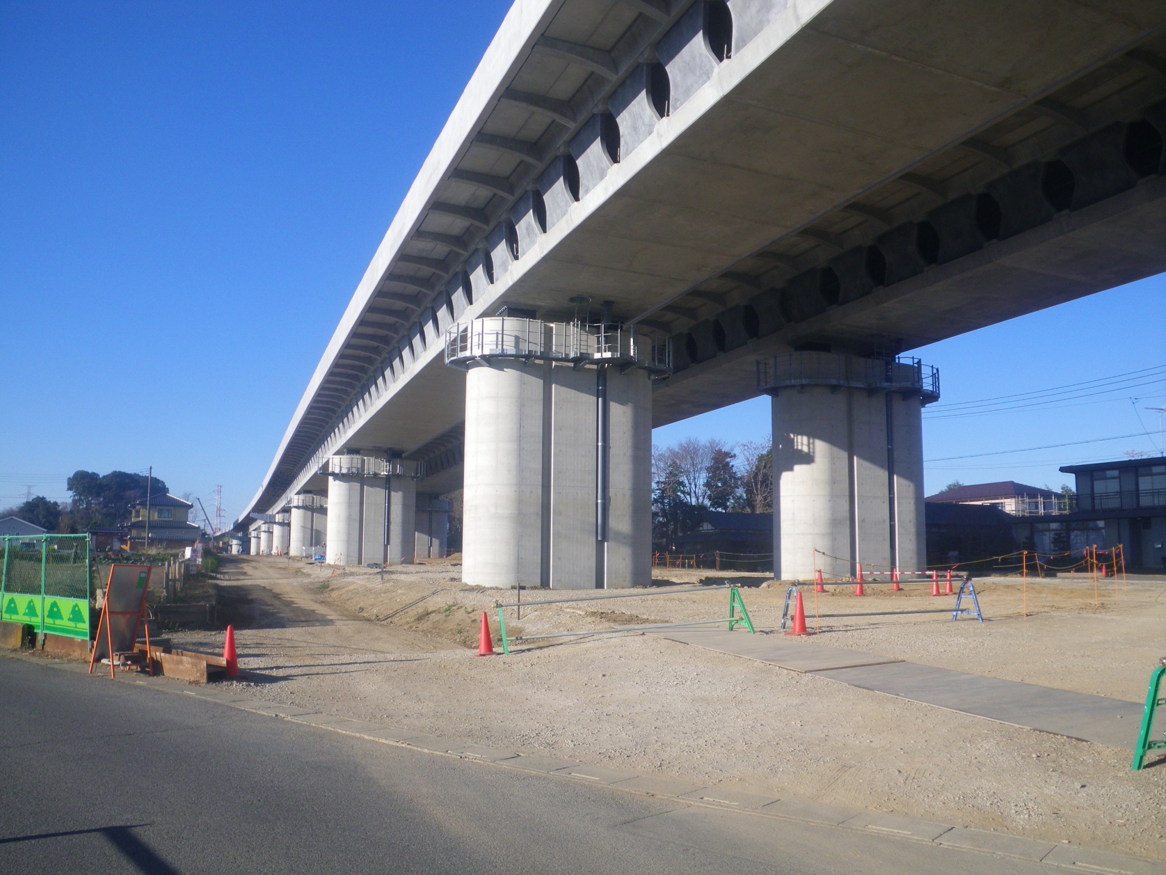
- Two slits are provided in each pier to reduce any oppressive feeling, making effective use of the interlocking reinforcement arrangement and allowing for installation of drainage pipes in the slits (Figure 7).
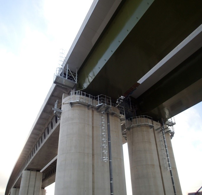
- The cross section of the girder is adjusted where it joins the adjacent
steel box girder bridge so as to improve the aesthetics as seen from nearby
houses and the main regional road (Figure 8).
 |
 |
| Figure 7 Drainage Pipe in Pier Slit | Figure 8 Joint Between PC Bridge and Steel Bridge |
4. Conclusion
This high-performance viaduct with excellent durability and seismic resistance was successfully designed and completed within about 18 months by bringing together bridge technology accumulated through past experience of expressway development. The completed viaduct fits well in the residential landscape.
Reference
1. Himoto, Ikeda, Nakatsumi, and Kaminaga (2014) “Design and Construction of Okegawa Viaduct No.2 in Metropolitan Inter-City Expressway,” Bridge and Foundation, November 2014, pp.5-12.